Example
Version: 1.0.0
This example will serve the purpose to set up a basic functioning OCPP server using the com.eurotech.framework.ocpp.driver.OcppDriver.
1. Create the Driver instance
Go in ESF Drivers and Assets and create a new driver. Select com.eurotech.framework.ocpp.driver.OcppDriver as Driver Factory, and use ocpp-driver for the Driver Name. Once created, in the driver parameters set the Hostname where the OCPP server must be listening to (127.0.0.1 should be fine for this example) and the Port (for convenience, set 3000 as it is the default port used by the simulator that we will use later).
2. Prepare the Wire Graph
Go in ESF Wire Graph section and create a graph like shown in the following picture (the components are described below):
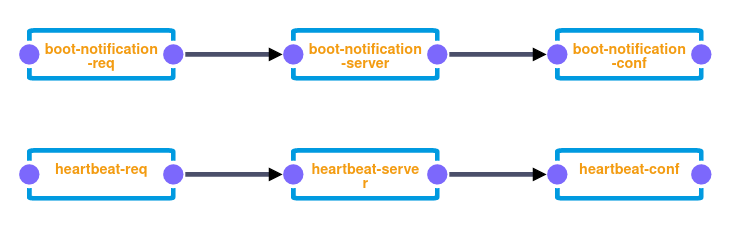
2.1. BootNotification flow
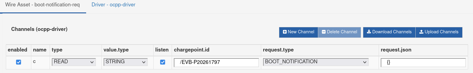
boot-notification-req
Create a new WireAsset under ocpp-driver called boot-notification-req containing one channel c set as below. This will be the entry point for BootNotification requests coming from the charge point that we will simulate later.
boot-notification-server
Create a new Javascript Filter called boot-notification-server setting the script property as below. This component will process the BootNotification request and return a corresponding result.
// Expect to receive a OcppDriverRequest
var ocppDriverRequest = JSON.parse(input.records[0].c.getValue());
var requestId = ocppDriverRequest.requestId;

// Build a dummy OCPP confirmation for the BootNotification request
var ocppConfirmation = { currentTime: new Date(), interval: 5, status: 'Accepted' };

// Wrap the OCPP confirmation into the OcppDriverResponse with the corresponding requestId
var ocppDriverResponse = { requestId: requestId, confirmation: ocppConfirmation };

// Return the OcppDriverResponse
var outRecord = newWireRecord();
outRecord.c = newStringValue(JSON.stringify(ocppDriverResponse));
output.add(outRecord);
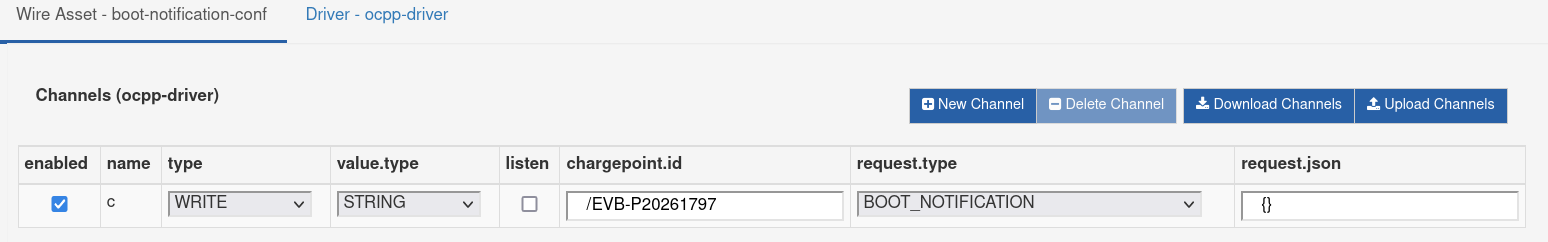
boot-notification-conf
Create a new WireAsset under ocpp-driver called boot-notification-conf containing one channel c set as below. This will be the driver asset that will send the response generated by boot-notification-server.
2.2. Heartbeat flow
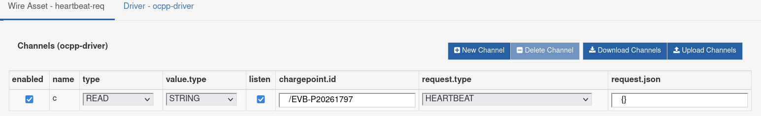
heartbeat-req
Create a new WireAsset under ocpp-driver called heartbeat-req containing one channel c set as below. This will be the entry point for Heartbeat requests coming from the charge point that we will simulate later.
heartbeat-server
Create a new Javascript Filter called heartbeat-server setting the script property as below. This component will process the Heartbeat request and return a corresponding result.
// Expect to receive a OcppDriverRequest
var ocppDriverRequest = JSON.parse(input.records[0].c.getValue());
var requestId = ocppDriverRequest.requestId;

// Build a dummy OCPP confirmation for the Heartbeat request
var ocppConfirmation = { currentTime: new Date() };

// Wrap the OCPP confirmation into the OcppDriverResponse with the corresponding requestId
var ocppDriverResponse = { requestId: requestId, confirmation: ocppConfirmation };

// Return the OcppDriverResponse
var outRecord = newWireRecord();
outRecord.c = newStringValue(JSON.stringify(ocppDriverResponse));
output.add(outRecord);
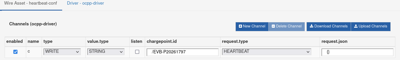
heartbeat-conf
Create a new WireAsset under ocpp-driver called heartbeat-conf containing one channel c set as below. This will be the driver asset that will send the response generated by heartbeat-server.
3. Simulate a OCPP Charge Point
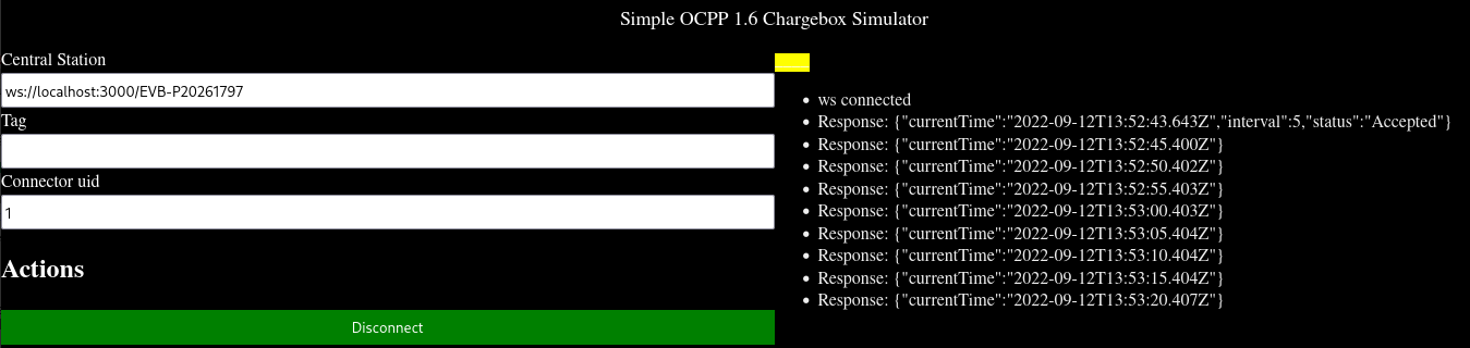
A simple OCPP 1.6 Charge Point simulator can be found here: https://github.com/victormunoz/OCPP-1.6-Chargebox-Simulator
Open the file simple simulator1.6.html with a browser.
Set the Central Station parameter to establish a new connection with our OCPP Driver (the default value should be fine). The value EVB-P20261797 is our example Charge Point ID that we set previously in the driver channels.
Click Connect.
The simulator performs the following actions:
- Establishes a Web Socket connection with our OCPP Driver
ocpp-driver, confirmed by the "ws connected" message; - Sends a BootNotification request, and if everything worked, should receive and show the corresponding BootNotification response generated by our
boot-notification-server; - Sends a Heartbeat request every N seconds as specified in the BootNotification confirmation, and receives the corresponding responses as generated by our
heartbeat-server.
4. Considerations
The steps shown in this example cover the more complex scenario of requests coming from the OCPP Charge Point, for which processing and logic is required in order to send back a response.
The components boot-notification-server and heartbeat-server represent the logic that must be implemented using the Driver. These are expected to be replaced with more complex and/or custom components.
Eventually, when it is required the logic to be off ESF, the OcppDriverRequest coming out of our *-req components can be sent to a separate system through a Publisher component. The external server can process such request and produce corresponding OcppDriverResponse objects that can be received by the gateway through a Subscriber component, and then forward them to the write channels.